Getting Started with the SO-101
 by Kevin Cloutier, April 21, 2026
The SO-101 was created by Hugging Face in collaboration with The Robot Studio. It was launched in April 2025 as an upgraded, low-cost, 3D-printable successor to the original SO-100 robot arm. It is a compact robot designed for studying imitation learning and data-driven control in a physical environment. It provides a simple, repeatable platform for collecting demonstration data and evaluating how learned policies can be transfered to commerical-grade hardware.
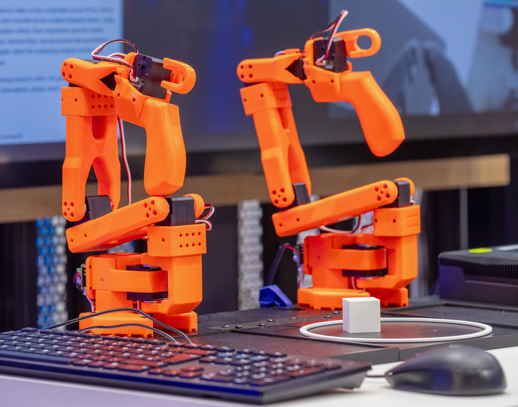
A typical setup uses two units: one to generate demonstrations through guided motion (the leader) and another to reproduce those behaviors under learned control (the follower). At Cloutier.engineer, the SO-101 is often deployed in dual-manipulation experiments that use two leaders and two followers. This configuration is described near the end of the guide when working with our custom Modular Experimentation Platform, which provides a stable foundation for repeatable experiments.
Procurement
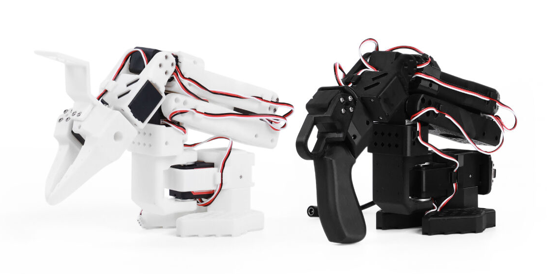
There are two main ways to get your hands on an SO-101. The simplest route is to buy a complete kit from a vendor like Seed Studio. At the time of writing, the kit is split into two components: the Motor Kit (~$290) and the 3D-Printed Skeleton (~$36). When ordering, I highly recommend choosing the Motor Kit Pro. The standard version uses the same motors for both the leader and follower, whereas the “Pro” uses optimized gear ratios that differ between the two arms. This difference makes the leader arm much smoother to manipulate by hand with the Pro set, while the follower arm benefits from more powerful, high-torque motors.
For my robots, I purchased the motors from Seeed Studio and 3D-printed the skeleton myself. Why? For starters, it's just more fun. But beyond the enjoyment, printing the parts offers a deep familiarity with the system that you simply don't get from a pre-built kit. It also gives you the freedom to modify parts or print replacements and additional units whenever you need them. As of today, I have created nearly a dozen of these in different colors, materials, etc. for different use cases, global events, and distributing them among colleagues.
Assembling the robot is fairly straight forward and can be completed within an hour. Just follower the Hugging Face video tutorials found here: Hugging Face SO-101 Assembly.
Development Setup
At this point, I assume you have procured and assembled at least one set of leader / follower arms. If you haven't, go do that and then come back, I can wait!
To set up the base development environment, we use Docker containers. This ensures a consistent, reproducible workspace. Because training of a model requires significant parallel processing, a host machine with a dedicated GPU is required at this point. Though, the intended workflow is to leverage a high-performance host hardware for the heavy lifting of model training while ultimately targeting embedded edge systems for real-time inference and deployment. For example, aqcuiring data and training a model on a server containing a NVIDIA 5060 and then deploying to an edge system like the AAEON UP Xtreme PTL Edge. Using Docker allows us to maintain a unified development environment that makes the transition from a powerful workstation to an edge device as seamless as possible.
Before proceeding, ensure you have the NVIDIA Container Toolkit installed on your host. This is required for the container to access the GPU's CUDA cores.Build the Image
Using the Starter Environment provided in the Resources section, build the image. The download contains a simple directory structure that is neccesary for our build. It also contains the Dockerfiles for both training (NVIDIA) and inference (Intel) stacks. The first step it to create an environment variable called SO101_HOME and set it to contains the location of the downloaded starter kit. Everything in this guide is relative to this download.
Open your bashrc file and edit it with your favorite editor:
# Open the file
sudo vi ~/.bashrc
Add your SO101_HOME path at the bottom like this:
export SO101_HOME=~/code/robotics/so-101
Then be sure to source the updated file
source ~/.bashrc
Now, using the $SO101_HOME environment variable we just created, we can build the image and run the training container:
# Move to the project root
cd $SO101_HOME

# Let's build!
docker build -t so101-base -f "$SO101_HOME/docker/nvidia/Dockerfile" .
While the build is running, let's allow the container to access the host display by adding the below to the bottom of your host ~/.bashrc file. This will come in handy later if you utilize running GUIs on the host from the container, such as the LeRobot training along with Rerun, etc. Open another terminal or tab and again use your favorite text editor (vi, of course!):
# Add this to the bottomg of your .bashrc to
# allow Docker containers to open windows on
# the host display
if [ -n "$DISPLAY" ]; then
   xhost +local:docker > /dev/null
fi
Again, changes to your bashrc file won't take effect until your next session. But you can source the file now to load the updates into your current session (only your current session, not any other windows or tabs you are running. e..g the tab installing the container). This isn't strictly necessary, but it does a good job of communicating an understanding of how this all works.
# source the updated file
source ~/.bashrc
Create the Container
Once the build completes, we can now run the container but before executing the code, let's examine some of the pesky arguments we are passing.
- --gpus - The gpus flag grants the container access to the GPUs on your system.
- --privileged and -v /dev:/dev - These are crucial for capturing data streams from cameras (/dev/video*) and communicating with the SO-101 motor controllers (/dev/ttyUSB* or /dev/ttyACM*).
- --shm-size=128g: - Prevents "bus error" crashes during training by providing enough shared memory for large robotic datasets.
- - v /run/user/$(id -u)/pulse - This is used to provide access from the container to the host speaker. This is handy when recording training data as the system can audibly tell you when to start and stop recording.
Ok, time to create the container:
docker run -it \
   --name so101 \
   --env="DISPLAY=$DISPLAY" \
   --env="XAUTHORITY=$XAUTHORITY" \
   --volume="$XAUTHORITY:$XAUTHORITY" \
   --volume="/tmp/.X11-unix:/tmp/.X11-unix:rw" \
   --gpus all \
   --privileged \
   --network host \
   --shm-size=128g \
   -v $SO101_HOME/so-101/resources/LeRobot:/LeRobot \
   -v /dev:/dev \
   -v /run/user/$(id -u)/pulse:/run/user/$(id -u)/pulse \
   -e PULSE_SERVER=unix:/run/user/$(id -u)/pulse/native \
   -v ~/.config/pulse/cookie:/root/.config/pulse/cookie \
   so101-base bash
Validation
Once the container has been created you will be dumped into an interactive session via bash. Sometimes you will see an error like this:
WARNING: Detected NVIDIA GeForce RTX 5060 Ti GPU, which is
not yet supported in this version of the container
ERROR: No supported GPU(s) detected to run this container
If you see this, it doesn't necessarily mean there is an problem. Run this python code to validate if your GPU stack is operational:
# This will confirm if you need to worry or not...
python3 -c "import torch; print(f'Device: {torch.cuda.get_device_name(0)}'); print(f'CUDA working: {torch.cuda.is_available()}'); x = torch.ones(1).cuda(); print('Tensor on GPU: Success')"
Now check that nvidia-smi is working:
nvidia-smi
Ensure your cameras are detected (if I haven't said this yet, your robots and cameras should all be connected to your host at this point).
v4l2-ctl --list-devices
A quick check to see if your robots are visible within the container
# find your SO-101 ports. Usually they are
# attached on /dev/ttyACM* or ls /dev/ttyUSB*
ls /dev/ttyUSB*
Robot Mounting
The SO-101 robots connect to the host computer via USB where they will automatically be mounted by the operating system. If you followed along with the validation steps detailed in the Dockerfile, you can see the robots mounted to locations such as /dev/ttyACM0, /dev/ttyACM1, etc. This is fine for quick-and-dirty testing, but for repeatbility we need to mount each robot into a known location every time. We can't be hunting for where the robots mounted each time we re-restart the devices, host, or container. Fortunately, this can be achieved with UDEV rules. So, let's leverage the tools provided by LeRobot to configure the mounting.
Quick side note:
LeRobot is an open-source robotics framework developed by Hugging Face for training and deploying imitation-learning policies on real hardware, such as the SO-101. The Docker container we are using here has this framework pre-installed, but it is not recommend to use in production-grade applications. LeRobot provides a unified set of datasets, models, and control abstractions that make it easy to collect demonstrations, train policies, and run them on your robots. I am using LeRobot as a reference toolchain for evaluating how different compute architectures handle real-time inference, control loops, and perception-to-action workloads, etc…. but don't use it in production.
You should still be connected to the container, but if not, let's get a session going:
docker exec -it so101 bash
As noted earlier, these steps can be used for one set of robots (e.g. a single leader and follower), or multiple sets. Just repeat these steps as many times as you need. Run the below command for each robot and follow the prompts. Once a robot mounting location is detected, the program will conclude and you will be presented with something simlar to: The port of this MotorsBus is /dev/ttyACM0. Take note of this location (e.g. write it down) and repeat this task for all robots:
# Be sure that each robot is connected to the host and
# powered-on. We use the lerobot provided application to
# easily find the current mounting point. Just follow
# the on screen directions
lerobot-find-port
With the mounting locations in hand, you now need to find the Serial Number, Product ID, and Vendor ID. This information will be used to create the UDEV rules. Again, be sure to take note of the output and keep your information organized for each piece of hardware:
# Let's get the serial number of each robot at each mounting location.
# Do this for every robot.
#
# Example:
#      udevadm info -a -n /dev/ttyACM0 | grep '{serial}'
#
udevadm info -a -n  | grep '{serial}'

# Similarly, now let's find the Product and Vendor IDs for the same robot
#
# Example:
#     udevadm info -a -n /dev/ttyACM0 | grep -E 'idVendor|idProduct' | head -n 2
#
udevadm info -a -n  | grep -E 'idVendor|idProduct' | head -n 2
With this output we can create a UDEV rule within /etc/udev/rules.d/. Note, this action must be completed on the host, not in the container. This is fairly straight forward in that we are creating a single entry for each robot, allowing us to guarantee the mounting location is the same every time we connect. The YOUR_DEVICE_NAME argument can be anything you wish it to be, but since this name is used throughout our interactions with the robots, it is usefull to follow a standardized naming convention. I recommend using the pattern so101-[leader|follower]-#. For example, the first set would be so101-leader-1 and so101-follower-1 with the last set so101-leader-n and so101-follower-n, and so on.
# NOTE: ON THE HOST MACHINE!
#
# The file may not already exist, that's ok
sudo vi /etc/udev/rules.d/99-usb-serial.rules

# Add the following line for each robot, replacing the ,
#  and  with the data acquired from
# the above steps along with the .
#
# Example:
#     SUBSYSTEM=="tty", ATTRS{idVendor}=="1a86", ATTRS{idProduct}=="55d3", ATTRS{serial}=="5AAF263434", SYMLINK+="so101-leader-1"
#
SUBSYSTEM=="tty", ATTRS{idVendor}=="", ATTRS{idProduct}=="", ATTRS{serial}=="", SYMLINK+=""
Now reload the rules and apply the changes:
sudo udevadm control --reload-rules
sudo udevadm trigger
Your devices will now be accessible at /dev/so101-*, let's verify:
# example: ls -l /dev/so101-*
ls -l /dev/
Now, if you run this same command within the docker container you should see the robot mounted there as well.
Motor Configuration
Each motor is identified by a unique ID on the bus. When brand new, these motors usually leave the factory with a default ID of 1. To be able to communicate with each motor, we need to set a unique ID for each (e.g. they can't all be 1). Additionally, the speed at which data is transmitted on the bus is determined by the baudrate, which also needs to be configured. The LeRobot framework provides a progam to complete both of these actions by writing the values into the motors' non-volatile section of internal memory (EEPROM). So we only need to do this once.
Important:
This process can only be done with one motor at a time. You have likely already wired all the motors together, that's ok, but you will need to disconnect them for this configuratation step. Each motor must be dircetly connected to the control board, by itself, for the ID and baudrate to be properly configured with the LeRobot helper software. Just follow the prompt to know which motor to connect and when.
Follower
Remember, if you have more than one Follower robot, you will repeat this step n times with the correct paramters identifying your robot. When running the below command you will see output similar to the following:
Connect the controller board to the 'gripper' motor only and press enter.
As instructed, you then plug-in the gripper's motor. Make sure it's the only motor connected to the board and that the motor itself is not yet daisy-chained to any other motor. As you press [Enter], the script will automatically set the ID and baudrate for that motor. You then see a message similar to the following:
'gripper' motor id set to 6
This is immediately followed by the next instruction:
Connect the controller board to the 'wrist_roll' motor only and press enter.
At this point you disconnect the gripper motor and connect the wrist_roll motor, repeating this operation for each motor as instructed. When you are done, the script will simply finish, at which point the motors are ready to be used. Repeat this step for additional Follower robots (not leader robots, that is a different configuration process shown in the next section).
# Example:
#
#   lerobot-setup-motors \
#      --robot.type=so101_follower \
#      --robot.port=/dev/so101-follower-1
lerobot-setup-motors \
   --robot.type=so101_follower \
   --robot.port=/dev/<MOUNT_LOCATION>
Leader
Similar to the configuration of the Follower robots, let's run the below for each Leader robot.
# Example:
#
#   lerobot-setup-motors \
#      --teleop.type=so101_leader \
#      --teleop.port=/dev/so101-leader-1
lerobot-setup-motors \
   --teleop.type=so101_leader \
   --teleop.port=/dev/<MOUNT_LOCATION>
Final Assembly
With both the leader(s) and follower(s) robot motors configured, you can now go ahead and connect all of the wiring, daisy chaining from the control board all the way to the gripper.
Calibration
Think of calibration as the “handshake” between your physical hardware and the control system. This allows us to align the Leader and Follower arms into a single, shared coordinate system. If the Leader's “90-degree” position doesn't perfectly match the Follower's “90-degree” position, your teleoperation will be jerky and inaccurate. Precise calibration ensures that when you move the Leader arm, the Follower mimics that exact spatial orientation in real-time. This 1-to-1 alignment is what allows you to record clean, high-quality data during imitation learning, which is the foundation for training a successful neural network policy.
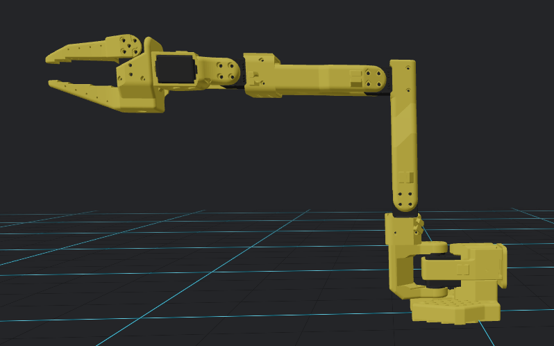
Before we run the calibration, we need to move the arm into a position where each motor is at it's mid point (e.g. the middle of it's available range). This can be seen in the below image. Note, depending on the hardware motors, the arm may not hold this position on it's own. Therefore, you will need to hold the robot as you run the command shown in the following step.
Then run the following command to calibrate the arm and follow the instructions on the screen:
lerobot-calibrate \
   --robot.type=so101_follower \
   --robot.port=/dev/<MOUNT_LOCATION> \
   --robot.id=<UNIQUE NAME>
Important:
The first time I did this I found that I was presented with a stacktrace error. This was due to the fact that a motor was installed into the body in a position where the servo horn was already maxed (or min'ed) out. Thus calibration would fail. The fix is to disconnect the horn, rotate it, reconnect, then recalibrate. The tricky part is determining which motor is the culprit, if you closely examine the error you will see the current position of the failing motor printed to the screen (but sadly not the motor ID). Therefore you can move one motor at a time and re-run the calibration until you find the correct motor causing the issue. At that point you need to unscrew the servo and change the servo horn orientation; hope you moved it the correct way; and cross your fingers it's the only motor in this state!
Once all of the follower arms are calibrated, move on to the leader arms:
lerobot-calibrate \
   --teleop.type=so101_leader \
   --teleop.port=/dev/<MOUNT_LOCATION> \
   --teleop.id=<UNIQUE_NAME>
Once completed, backup the calibration files so you don't have to do this again (e.g. if you recreate the docker container you can reuse the calibration data). I have stored these files for my robots in the repository as an example of what these files contain, but they are specific to my robots:
$SO101_HOME/resources/data/calibration
Looking at the above directory will see folders for teleoperators and robots. The former contains calibration files for the leader arms, the latter the follower arms. Note the names of the files correspond to the IDs of the robots you created earlier.
Camera Configuration
Imitation learning is a machine-learning paradigm in which a model learns to perform a task by observing and mimicking expert demonstrations rather than being explicitly programmed. In practice, the system captures the expert's actions, such as steering, grasping, or navigation, alongside the corresponding sensory inputs, and then trains a policy that maps those inputs to the same actions. To provide the necessary visual context, one or more cameras are required to record the demonstration scenes where multiple viewpoints improve robustness by covering occlusions and offering richer spatial cues. In the SO-101 setup, we use at least one “world camera” and one “on-robot camera”:
- World Camera: This is a stationary, external camera that records the entire scene from a fixed viewpoint, providing a global view of the environment and the robot's interactions. In our use case, the World Camera is mounted above the robots.
- On-Robot: This camera is mounted on the robot itself (typically on the head, arm, wrist, or end-effector) and captures the robot's immediate surroundings from its own perspective, enabling the system to perceive the objects and spatial relationships it manipulates.
These cameras record synchronized video, while we also record sensor data (e.g. motor positions from the motors we already configured) for use later within the imitation-learning pipeline. In simpler terms, recording the data allows us to then train a model from these contexts later. So, first we acquire training data, then later we train a policy with this data.
The LeRobot framework supports two types of cameras, RealSense and OpenCV. In our setup we use a RealSense camera as the World Camera and an OpenCV camera as the On-Robot / Wrist camera. Similar to the motor configuratuion above, every camera requires a unique identifier to be instantiated. This allows the system to distinguish between multiple connected devices. Both OpenCV and RealSense cameras support auto-discovery so it is fairly straight-forward to identify the hardware. Ensure your cameras are connected and run the below command in the CONTAINER:
# This command will search for all attached cameras and
# save a frame to your disk, reporting the location
# of the saved images in the output. At this point we are not concerned
# with the output.
#
# What we are concerned with is errors as these are usually tied to the
# cameras failing. Most often this is due to physical limitations on the
# USB hub or port you have selected. If you see errors, try to ensure that
# each camera has it's own USB port such as one on the front of the PC, one
# directly connected to the motherboard via the back... basically, attemmpt
# to use different busses if possible.
#
lerobot-find-cameras opencv --output-dir $HF_LEROBOT_HOME/find-cameras  # or realsense for Intel Realsense cameras
The output for each camera will be similar to the below, note that this particular model reveals the mounting location (/dev/video2), they don't always:
--- Detected Cameras ---
Camera #0:
   Name: OpenCV Camera @ /dev/video2
   Type: OpenCV
   Id: /dev/video2
   Backend api: V4L2
   Default stream profile:
      Format: 16.0
      Fourcc: UYVY
      Width: 640
      Height: 480
      Fps: 30.0
Similar to how we used the lerobot-find-port program above, we can use this information to update the UDEV rules to mount each camera in a specific location every time it is connected. The easisest way to do this is to unlplug all but one camera, then run the lerobot-find-cameras program again and use the information to create new UDEV rules.
RealSense
For RealSense cameras, we need the physical mounting point from the lerobot-find-cameras command to determine the serial number. Detach all other cameras, and run the below, searching for the Physical port:
lerobot-find-cameras realsense --output-dir $HF_LEROBOT_HOME/find-cameras
You should see a Physical port attribute that looks like the below. This outpout is letting us know that the camera is mounted at /dev/video0:
/sys/devices/pci0000:20/0000:20:08.1/0000:24:00.3/usb2/2-1/2-1:1.0/video4linux/video0
Therefore, on the host computer we can easily query the device and determine its serial number like so:
# Example:
#
#     udevadm info --attribute-walk --name=/dev/video0 | grep 'ATTRS{serial}'
#
udevadm info --attribute-walk --name= | grep 'ATTRS{serial}'
Again, on the host, we use the serial number to create a udev rule adding it to /etc/udev/rules.d/99-lerobot-cameras.rules on the host. here is an example line.
# Example:
#
#     SUBSYSTEM=="video4linux", ATTRS{serial}=="319543021373", SYMLINK+="so101-follower-realsense_main_world_cam"
#
SUBSYSTEM=="video4linux", ATTRS{serial}=="", SYMLINK+=""
When finished, reload UDEVADM:
sudo udevadm control --reload-rules
sudo udevadm trigger
OpenCV Cameras
OpenCV cameras are a bit different. Often the serial number is not unique between hardware devices of the same make and model. For example, if you have two of the same gripper cameras (e.g. you have two Follower arms, one each contaning a wrist camera) they may show the same serial number when using the method defined for RealSense cameras above. Surely try it first, but many times we need to use the KERNELS attribute for these devices and augment our UDEV rule to accept it. The KERNELS attribute is a key that searches the device path upwards (checking the device itself and its parent devices) for a matching kernel device name. It can be used to uniquely identify hardware by its position in the system hierarchy, such as the specific USB port it is connected to, rather than its unpredictable name. This can be gathered by running the below command:
Note:
Unlike the method for RealSense cameras, this UDEV setting is tied to the USB port being used. If you move the camera to a different port, you will need to update this rule.
For OpenCV cameras, we also need the physical mounting point from the lerobot-find-cameras command to determine the serial number. Detach all other cameras, and run the below, searching for the ID attribute:
lerobot-find-cameras opencv --output-dir $HF_LEROBOT_HOME/find-cameras
You should see a ID attribute that looks like the below. This outpout is letting us know that the camera is mounted at /dev/video6:
--- Detected Cameras ---
Camera #0:
Name: OpenCV Camera @ /dev/video6
Type: OpenCV
Id: /dev/video6
Therefore, on the host computer we can easily query the device and determine the kernels information like so:
# Example:
#
#    udevadm info --attribute-walk --name=/dev/video6 | grep "KERNELS==" | head -n 2
#
udevadm info --attribute-walk --name=/ | grep "KERNELS==" | head -n 2
Once you have defined your UDEV rules for each OpenCV camera, open the same file you used for the RealSense cameras (/etc/udev/rules.d/99-lerobot-cameras.rules) and add a line for each OpenCV camera.
When finished, reload UDEVADM:
sudo udevadm control --reload-rules
sudo udevadm trigger
Camera Validation
When you have completed the new UDEV rules, ensure they work by listing the devices and reviewing the simlinks on the HOST and the CONTAINER:
#
#  This command assumes you used the naming conventions supplied above (e.g. so101*)
#
ls -l /dev/so101*
And finally, if you examine the command we have been running, you will see it is saving test images to $HF_LEROBOT_HOME/find-cameras. Go ahead and look in that directory to see the images, but you should run them again to make sure eveyrthing is working as desired:
lerobot-find-cameras realsense --output-dir $HF_LEROBOT_HOME/find-cameras
lerobot-find-cameras opencv --output-dir $HF_LEROBOT_HOME/find-cameras
Validation
To verify your setup, the best “smoke test” is a teleoperation session. This confirms that your motor IDs, baud rates, and calibrations are all perfectly synced. When you move the Leader arm, the Follower should mirror its movements with near-zero latency.
What you should be looking for as you run through your first session:
- Responsiveness: The Follower should shadow the Leader's orientation immediately.
- Smoothness: If the Follower jitters or snaps to positions, calibration is likely off, do it again.
- Torque Check: If the Follower feels “weak” and cannot hold its own weight, ensure you are using a high-quality 12V power supply capable of at least 5A.
Teleoperation
Within your Docker container, run the following command for each set of robotic arms. If you have two sets of robots and wish to operate them simultaneously for dual-manipulation, you will need two terminal sessions.
# Once the below command is executed, the Follower arm
# will immediately reposition into the same pose as
# the Leader. Therefore, ensure both arms are in similar
# starting positions to avoid a jerking start as the Follower
# repositions to match the Leader.
#
# Format:
#
#     lerobot-teleoperate \
#        --robot.type=so101_follower \
#        --robot.port=/dev/ \
#        --robot.id= \
#        --teleop.type=so101_leader \
#        --teleop.port=/dev/ \
#        --teleop.id=
#
lerobot-teleoperate \
   --robot.type=so101_follower \
   --robot.port=/dev/so101-follower-1 \
   --robot.id=so101-follower-1 \
   --teleop.type=so101_leader \
   --teleop.port=/dev/so101-leader-1 \
   --teleop.id=so101-leader-1
Once you've confirmed that you can manually control the arm, you are officially ready to begin data collection for training your first AI policy. But one more thing remains before you can go off and running on your own…
The Modular Experimentation Platform
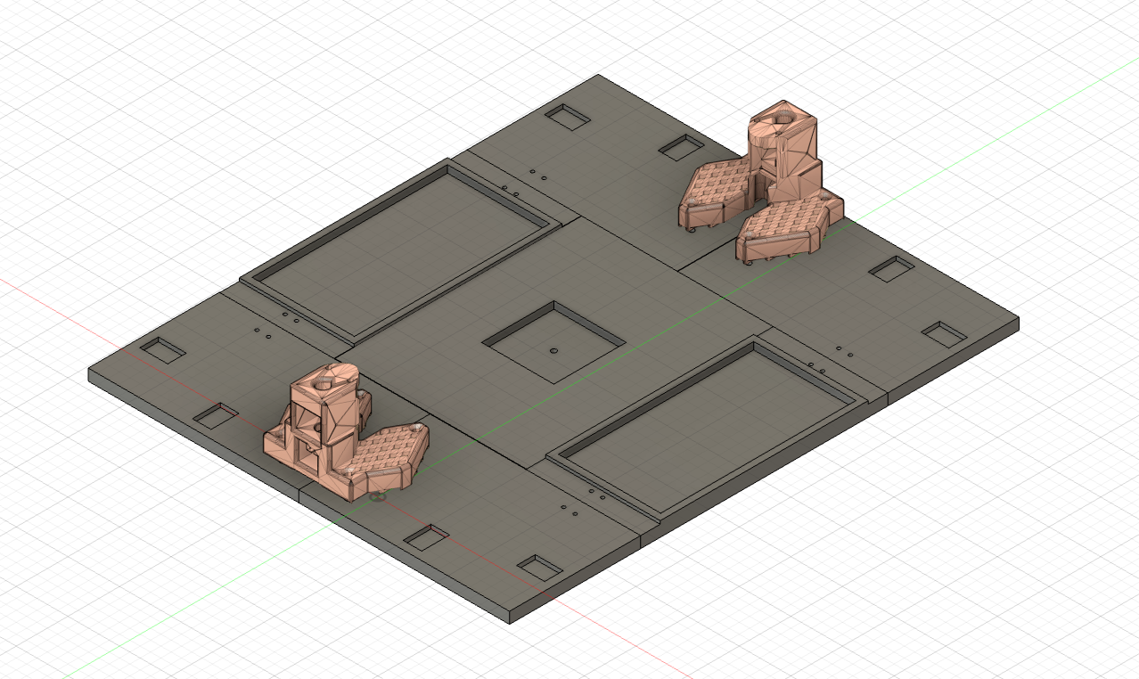
The Modular Experimentation Platform is a standardized dual-arm robotics testbed I designed for rapid experimentation, repeatable demonstrations, and multi-task manipulation. It provides fixed mounting points for two SO-101 follower arms, defined pick locations, and an interchangeable “game board” surface that supports tasks like pick-and-place, stacking, tic-tac-toe, checkers, the classic Tower of Hanoi, and more.
The platform integrates with multiple camera setups (world, wrist, etc.) by including 3D-printed AprilTags. This makes perception setup fast and consistent across experiments whether in your lab or on the road. Everything is fully 3D-printable and assembles with a handful of M4 nuts and screws. Using this platform you can reproduce the exact geometry for your demos anywhere in the world. Download the files below to print your own.
Precision Engineering
High-reliability embedded systems, FPGA design, and robotics platforms built with uncompromising attention to detail.
Verified Performance
Benchmarked, stress‑tested, and validated across real‑world robotics and compute workloads.
Robotics & Control
Physical systems, precise motion, and intelligent actuation.