Universal Robots UR5e
 by Kevin Cloutier, May 13, 2026
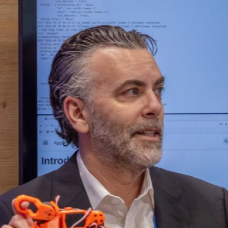
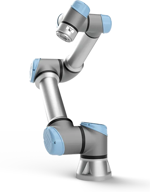
The UR5e is ideal for applications requiring a collaborative robot that is light enough to be mounted within an existing workspace, such as on a bench or integrated into a test cell. With a reach of 850 mm and the ability to handle light to medium payloads, the UR5e is well suited for manipulation tasks that require precision, repeatability, and safe human-robot interaction.
Spec |
Value |
|
|---|---|---|
Part Number |
||
Unit Price |
$34,527 USD |
|
Weight |
34.4 kg |
|
Dimensions |
915 x 760 x 485 mm (L x W x H) |
|
Mounting the Robot
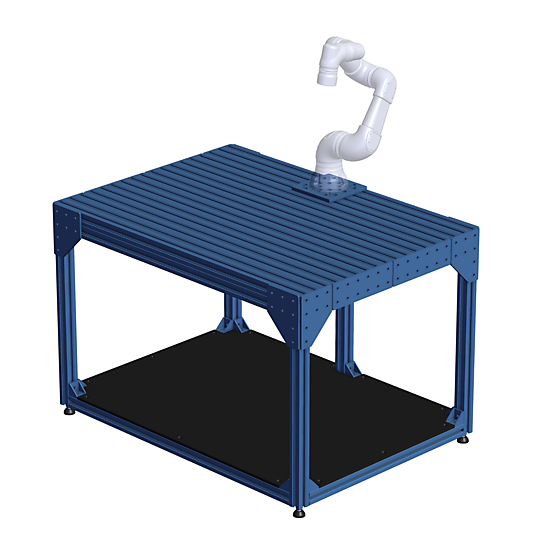
There are numerous ways to mount the Universal Robots UR5e, but unless otherwise specified, all experiments here utilize the Vention Small Robot Workstation. This lab-grade workstation provides a stable environment for the cobot while offering ample surface area to integrate peripherals, such as conveyor belts, directly into the experimental setup.
If you do not have access to this specific workstation, you may use an alternative mounting solution; however, please be aware that all experiment configurations are calibrated to this hardware. Specifically, the robot origin, camera transforms, and sensor locations assume the dimensions and mounting points of the Vention workstation as seen in the image below (e.g. the robot is positioned on the far edge rail, centered horizontally).
Preparing the Robot
The robot needs to be prepared before it can be used via ROS2. There are two ways one can control the robot via a network connection:
- Remote control: Full control is given to the client, enabling it to power on and off, brake release, load PolyScope programs, and send URScript programs directly to the controller.
- External Control URCap: Control remains on the tech pendant, with external commands being sent from the network to the External Control URCap which injects the needed URScript code from the client library. This makes it possible to combine the use of the client library and other PolyScope program nodes, like standard moves or other third-party URCaps.
We will utilize both of these control methods throughout ARC.
Network Connection
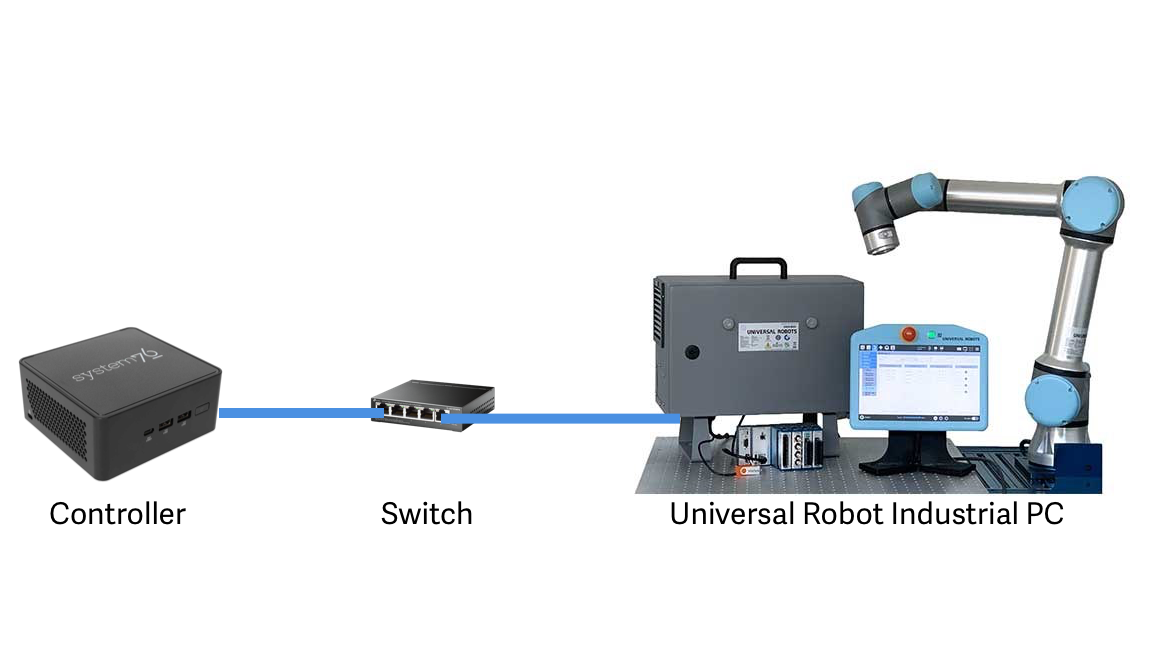
While the Universal Robots documentation recommends a direct connection between the control system and the UR industrial computer for optimal performance, incorporating a network switch offers greater flexibility for our demonstration setup. This configuration allows additional devices or controllers to be connected simply by plugging in Ethernet cables. Any delay introduced by the switch has proven to be imperceptible for our research. Using the image below as a guide, connect the mini-pc controller to the UR5e via a tp-link 5-port Giugabit Switch (or similar) and a couple ethernet cables.
The ethernet port is inside the case. Grab the key, open the cabinet and find the port. Route a cable through one of the openings in the bottom and plug in. Then connect the other end of the cable to the ethernet switch. See the yellow cable in the picture below:
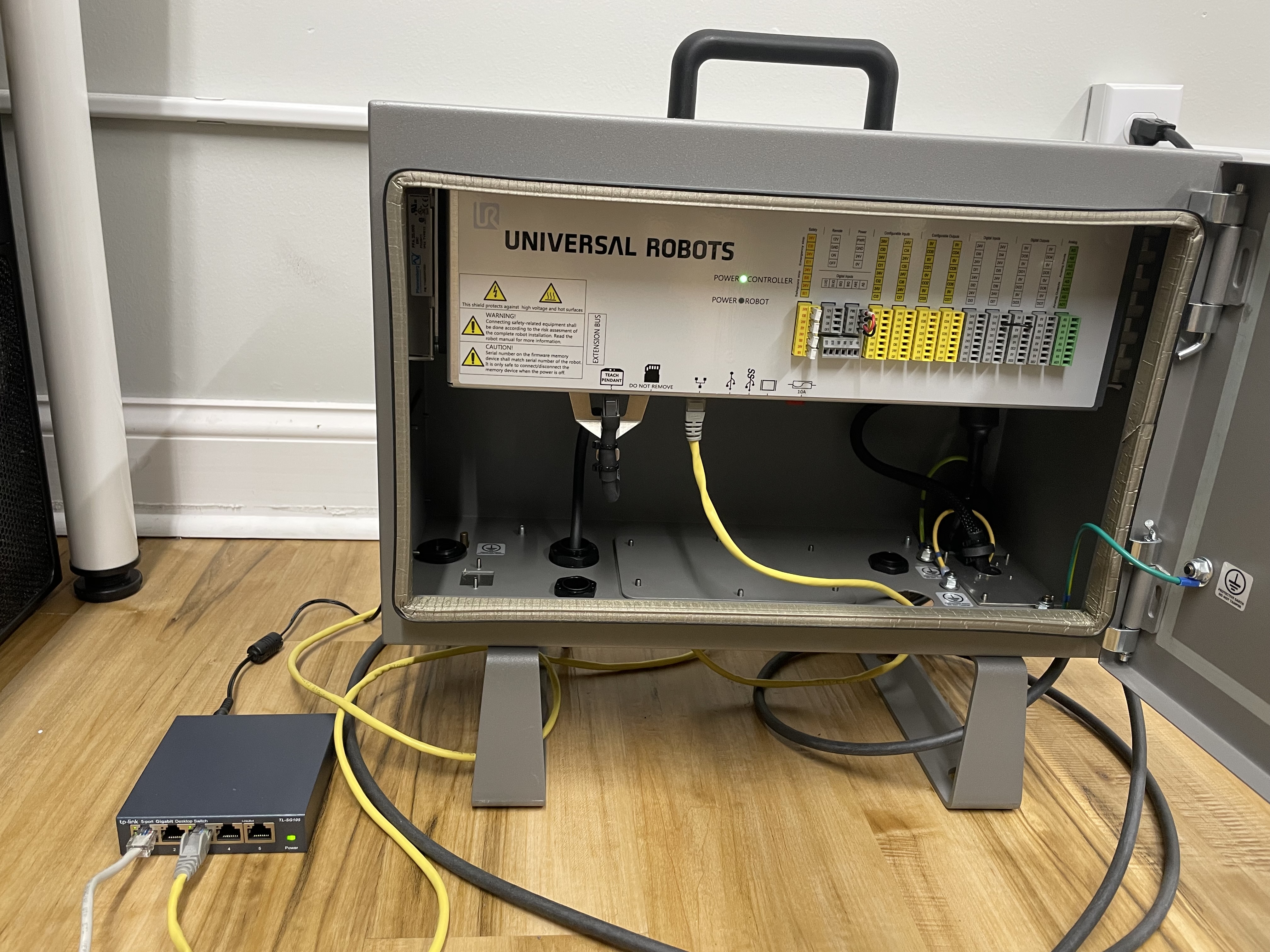
Configuring the network connection is completed via the wired pendant using PolyScope. Open the network settings from the pendant (Setup Robot -> Network) and enter these settings (or select your own):
Setting |
Value |
|---|---|
IP address |
192.168.10.2 |
Subnet mask |
255.255.255.0 |
Default gateway |
192.168.10.1 |
Preferred DNS server |
192.168.10.1 |
Alternative DNS server |
0.0.0.0 |
Testing is simple, just use the controller (or any PC on the same network) to send a ping to the industrial pc. If a response is received you are good to go. If not, time to debug.
# From the controller:
ping 192.168.10.2
Enabling Services
If using PolyScope 5.10 or greater you must enable services:
- Go to the hamburger menu -> Settings -> Security -> Services
- Unlock the menu using the admin password.
- Enable the Dashboard Server, Primary Client Interface and Real-Time Data Exchange (RTDE) interfaces (see image below).
- Lock the menu and press exit.
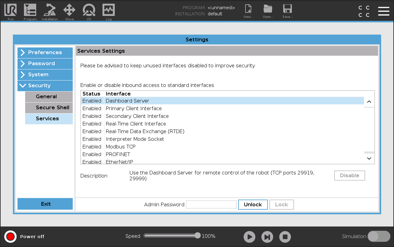
Enabling Remote Control
As mentioned above, one of the two control methods supported by ARC is via “remote control”. Before being able to use this functionality it must be enabled within the settings:
- Go to the hamburger menu -> Settings -> System -> Remote control.
- Unlock the menu using the admin password, and enable Remote Control.
- Press exit.
The robot can now be toggled between local and remote control in the upper right hand corner as seen in the below image. Note, this toggle does not persist between power cycles.
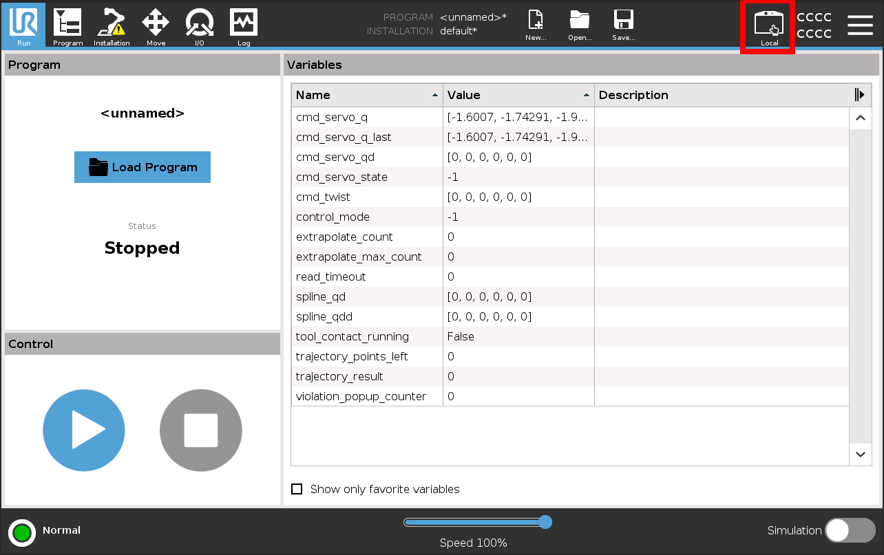
External URCap
The second control method used within ARC is via an external URCap. URCaps are a software extension installed on the robot's industrial PC that enables seamless integration with third-party hardware, peripherals, or application-specific functionality. Unlike the built-in system features, an external URCap providies a standardized way to add new capabilities such as grippers, vision systems, or communication protocols. By leveraging the framework, external modules appear natively within the robot's teach pendant interface, allowing users to configure and operate them as if they were part of the core system.
The External Control URCap (externalcontrol-1.0.5.urcap) is an official Universal Robots extension that enables remote control of a UR5e from a connected PC, integrating with the UR ROS2 drivers, and the Universal Robots Client Library via a native program node on the teach pendant. To install it you first have to copy it to the robot's programs folder which can be done either via scp or using a USB stick attched to the teach pendant.
On the welcome screen click on the hamburger menu in the top-right corner and select Settings to enter the robot's setup. There select System and then URCaps to enter the URCaps installation screen. There, click the little plus sign at the bottom to open the file selector. There you should see all urcap files stored inside the robot's programs folder or a plugged USB drive. Select and open the externalcontrol-1.0.5.urcap file and click open. Your URCaps view should now show the External Control in the list of active URCaps and a notification to restart the robot.
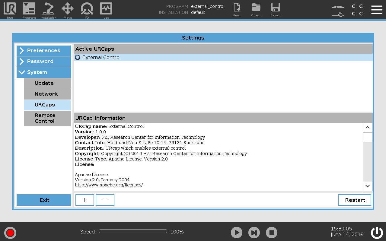
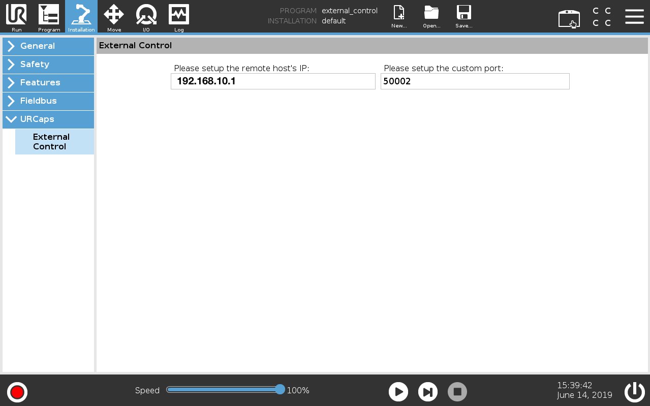
After rebooting, you should find the External Control URCaps inside the Installation section. To see this, select Program Robot on the welcome screen, select the Installation tab and select External Control from the list. Here you'll have to setup the IP address of the external PC which will be running the ROS driver. If you kept the IPs the same in the Network Connection Setup section, then it should be 192.168.10.1. The custom port should be left untouched for now.
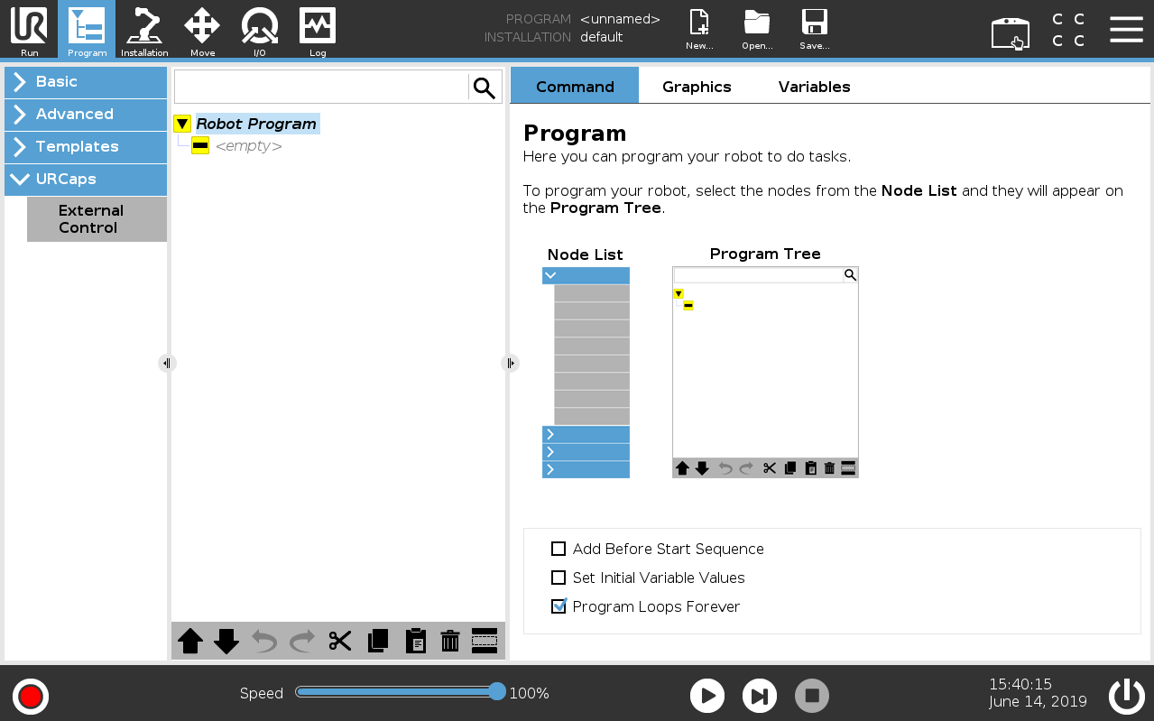
Using the new URCap is straightforward. Create a new program, insert the External Control node into the program tree, and click play. But remember, this program needs to be running every time you wish to control the robot via the External Control URCap.
Setting the Home Pose
Each experiment expects the robot to be in a specific starting postion. Most experiments will work without setting the robot to “home”, but skipping this step can introduce unpredictable startup behaviors when the arm attempts to meet it's next waypoint. Therefore, set a home postion in the tech pendant and ensure the robot is in this position before executing each experiment.
- Open Installation: On the teach pendant, tap the Installation button in the header. Navigate to Home: In the side menu, go to the General section and select Home. Position the robot: Move the robot arm matching the below table:
- Save the position: Once the arm is in place, tap Set Position on the screen. This saves the robot's current joint angles as the new home position.
Joint |
Position |
|---|---|
Base |
180° |
Shoulder |
-100° |
Elbow |
104° |
Wrist 1 |
0° |
Wrist 2 |
90° |
Wrist 3 |
0° |
Gripper |
Open |
Control System Integration
With the physical setup complete and the chosen controller connected to the switch, we now need to configure the network settings. If the controller is already connected to the internet via Wi-Fi, that connection can remain active, it will not interfere with communications to the UR machine.
On the controller, open
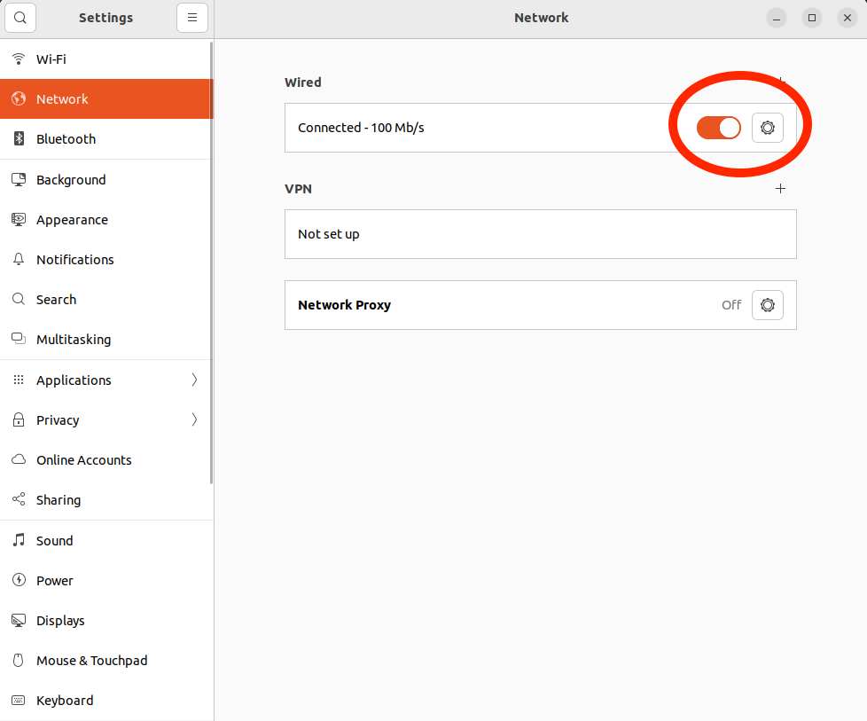
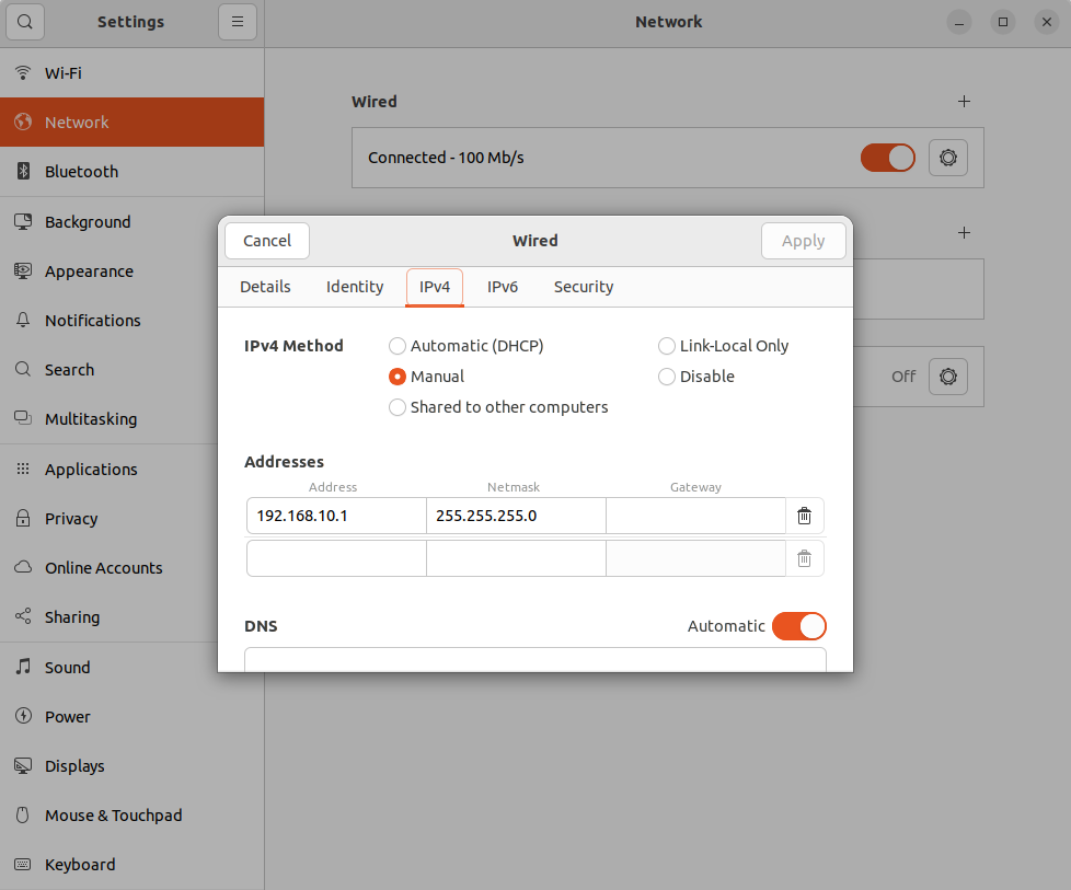
Select manual and enter the ip address, again, in this setup we are using the address provided eariler. Note, also check the box labeled “Use this connection only for resoruces on its network”. This is not seen in the below image, one must scroll to the bottom of the pop-up box to see it.
Docker Setup
Communication and control of the UR5e is completed via docker containers on the selected controller. Each demonstration may have it's own container, but following along with the steps in this section provides the reader with a hands-on understanding of the infrastructure as well as an end-to-end test that validates the system setup. Using Docker containers ensures each demonstration is repeatable on multiple platforms while at the same time making setup a breeze. Looking at the example docker file, one can see it is derived from a NVIDIA Isaac image. This image includes most of what we need out-of-the-box, such as ROS2 Humble. Looking closely you can see we are adding additional libraries such as the Universal Robots Client and Robot drivers. These are needed for most solutions that utilize this UR5e robot.
Universal Robots Client Library
The Universal Robots Client Library provides a C++ interface for communicating with Universal Robots controllers over their real-time data exchange (RTDE) protocol. It is designed as a lightweight, dependency-free library that allows developers to send commands and receive state information directly from the robot. By installing this package, users gain access to a stable API for building custom applications, integrating external control systems, or extending robot functionality without needing to implement low-level socket communications themselves. This library serves as the foundation for higher-level drivers and ensures reliable, real-time interaction with the UR5e and other e-Series robots.
Universal Robots ROS Driver
The Universal Robots ROS Driver is the official ROS integration layer that connects Universal Robots hardware with the ROS ecosystem. It builds on the Client Library to provide a complete driver that exposes robot state, publishes joint and tool data, and accepts trajectory commands through standard ROS topics and services. With this package installed, the UR5e can be controlled using ROS tools such as MoveIt, enabling motion planning, simulation, and application-specific workflows. The driver also supports features like safety configuration, calibration, and external control via URCaps, making it the central component for deploying Universal Robots in robotics research and production environments.
Build and Run the Container
Note:
These steps assume you are deploying the container to Intel (x86) target hardware. If you are looking to build the container and image on a different platform, such ass the the NVIDIA DGX Spark workstation, the process is the same but the dockerfile is different (e.g. use the dockerfile.aarch64)
Open the terminal and CD into the directory containing the docker file:
cd platforms/ur5e/docker
Build the image with the following:
docker build -t reach-controller -f dockerfile.x86_64 .
Now we want to run the container for the first time:
docker run -it \
    --network=host \
    --privileged \
    -v /dev/bus/usb:/dev/bus/usb \
    --device-cgroup-rule='c 189:* rmw' \
    -v $ARC_HOME/platforms/ur5e/:/app \
    --name reach-controller-dev \
    --device /dev/accel \
    --device /dev/dri \
    reach-controller \
    bash
Validate the Container
Once the container has started, you will be placed in the /app dircetory, which also maps the local ARC project. This structure contains a simple python script that can be run to verify that all three hardware devices (CPU, iGPU, and NPU) are properly configured and accessible within the container. The script is called device_check.py and it is found in the resources dircetory, let's execute it:
cd /app

python3 test/device_check.py
The output should appear similar to the below:
Device: CPU | Name: Intel(R) Core(TM) Ultra 7 255H
Device: GPU | Name: Intel(R) Graphics [0x7d51] (iGPU)
Device: NPU | Name: Intel(R) AI Boost
Lastly, let's ensure that ROS2 is functioning by simply running the classic TALKER and LISTENER examples privided by ROS. In one terminal, the TALKER node continuously publishes messages to a specific topic, while in another terminal the LISTENER node subscribes to that topic, receives the messages, and prints them to the screen. If successfull, this demonstrates that ROS 2 is correctly installed and comnuications are working as intended. In your current terminal:
# start the **TALKER**
ros2 run demo_nodes_cpp talker
You should see the messages being sent to the topic. Now, in another tab, open another interactive session with the container and execute the listener:
# Attach an interactive session to the container
docker exec -it reach-controller-dev bash

# Run the listener
ros2 run demo_nodes_cpp listener
You should see the listener printing the messages from the talker.
[INFO] [1765206801.238282217] [listener]: I heard: [Hello World: 1]
[INFO] [1765206802.238450543] [listener]: I heard: [Hello World: 2]
[INFO] [1765206803.238610348] [listener]: I heard: [Hello World: 3]
[INFO] [1765206804.238461407] [listener]: I heard: [Hello World: 4]
[INFO] [1765206805.238698831] [listener]: I heard: [Hello World: 5]
...
Normal Usage
In the future, starting the container and attaching an interactive session is simple:
# Start the container
docker start reach-controller-dev

# Attach an interactive session
docker exec -it reach-controller-dev bash
If you want to remove the container and image, it's also straightforward:
# Stop the container
docker stop reach-controller-dev

# Remove the container
docker container rm reach-controller-dev

# Remove the image
docker image rm reach-controller
Start the Universal Robots ROS2 Driver
There are muiltiple ways to start the ROS2 driver, but Universal Robots recommendeds using the ur_control.launch.py launchfile supplied in the driver package. This starts the driver, a set of controllers, and a couple of helper nodes. The only required arguments are the ur_type and robot_ip. In the below we also use headless_mode, and ensure rviz does not launch (launch_rviz:=false). If we wished to override the controllers configuration file, that could be done with a controllers_file argument but is unecessary here:
# Ensure yout container is started
docker start reach-controller-dev

# Attach an interactive session
docker exec -it reach-controller-dev bash

# Start the ROS2 driver
ros2 launch ur_robot_driver ur_control.launch.py \
ur_type:=ur5e \
robot_ip:=192.168.10.2 \
headless_mode:=true \
launch_rviz:=false
Calibration Information
Each UR robot is calibrated inside the factory providing exact forward and inverse kinematics. To make use of this in ROS, you have to extract the information from the robot. Though this step is not necessary to control the robot using this driver, it is highly recommended, otherwise the endeffector positions could be off by centimeters or more.
If you are following along step-by-step, then the driver is currently running in the foreground of your terminal. Now open another terminal, attach a second interactive session, and let's extract the calibration data:
    # Attach an interactive session
    docker exec -it reach-controller-dev bash

    # Extract calibration data
    ros2 launch ur_calibration calibration_correction.launch.py \
    robot_ip:=192.168.10.2 target_filename:="/app/platforms/ur5e/config/ure5_calibration.yaml"
Note:
The target_filename is saved under the app within the container. Examining the dockerfile reveals that this directory is mounted from the host system. Therefore, saving files to app within the container is saving to the actual host whereas app is the root of the codebase.
You should see output similar to the below:
robot_ip:=192.168.10.2 target_filename:="/app/my_robot_calibration.yaml"
[INFO] [launch]: All log files can be found below /root/.ros/log/2025-10-14-12-36-00-133654-2a238eba60cb-89
[INFO] [launch]: Default logging verbosity is set to INFO
[INFO] [calibration_correction-1]: process started with pid [90]
[calibration_correction-1] [WARN] [1760459760.220634010] [UR_Client_Library:]: Failed to read from stream, reconnecting in 1 seconds...
[calibration_correction-1] [INFO] [1760459761.822396294] [ur_calibration]: checksum: [4294967295 4294967295 4294967295 4294967295 4294967295 4294967295 ]
[calibration_correction-1] dh_theta: [1.87638179299787e-08 -0.349376632441425 6.8451179881476 -0.212557480523727 6.42209883546657e-07 -2.55478023240135e-07 ]
[calibration_correction-1] dh_a: [0.000209739004375459 -0.399625591300979 -0.383569463636146 8.17047484602284e-05 2.28811277595212e-05 0 ]
[calibration_correction-1] dh_d: [0.162646962461696 136.630145667482 -115.841810655261 -20.6548822178315 0.0996897807302608 0.09949401385059 ]
[calibration_correction-1] dh_alpha: [1.57139382931003 -0.00106560194816154 0.00398210851299615 1.56946240427087 -1.570064887322 0 ]
[calibration_correction-1] calibration_status: 1
[calibration_correction-1]
[calibration_correction-1] [INFO] [1760459761.923020273] [ur_calibration]: Writing calibration data to "/app/my_robot_calibration.yaml"
[calibration_correction-1] [INFO] [1760459761.923680389] [ur_calibration]: Wrote output.
[calibration_correction-1] [INFO] [1760459761.923753123] [ur_calibration]: Calibration correction done
[INFO] [calibration_correction-1]: process has finished cleanly [pid 90]
If successfull, you have extracted the calibration data from your robot. Remember, these are different for every robot so it is important to extract your own copy from your hardware. Now that this is done, exit both terminal sessions. You can kill the ROS2 driver by simply typing ctrl-x, then type exit into each window. With all interactive sessions closed, the container should shutdown. Verify the container does not appear in the output of ps
docker ps
Now that we have the calibration data, we can restart the ROS2 driver and pass the kinematics file in at launch. Again, in one terminal run the below:
# Attach
docker exec -it reach-controller-dev bash

# Launch
ros2 launch ur_robot_driver ur_control.launch.py \
    ur_type:=ur5e \
    robot_ip:=192.168.10.2 \
    headless_mode:=true \
    launch_rviz:=false \
    kinematics_params_file:=/app/platforms/ur5e/config/ure5_calibration.yaml
Let's Move!
Everything is setup and you are ready to move the robot. First step, be sure your robot has enough room to move in any direction. It's easy to get the front and back confused, thus on this first test be sure there is enough room for the robot to completely stretch out until you are sure which is front, back, left, right, etc. Let's move the arm into a home pose.
Note:
Important: The robot must be turned on, and placed into REMOTE mode as described above (Enabling Remote Control) for this example. This is NOT necessary for every use of the robot, but it is necessary for this test.
# In a second terminal
docker exec -it reach-controller-dev bash
Now run this code in the second terminal, it will move the robot:
ros2 action send_goal \
/scaled_joint_trajectory_controller/follow_joint_trajectory \
control_msgs/action/FollowJointTrajectory \
"{
   trajectory:
   {
      joint_names: ['shoulder_pan_joint', 'shoulder_lift_joint', 'elbow_joint', 'wrist_1_joint', 'wrist_2_joint', 'wrist_3_joint'],
      points: [
         {
            positions: [3.1416, -1.744, 1.812, 0, 1.5708, 0.0],

            time_from_start: {sec: 6}
         }
      ]
   }
}"
Continuing, let's move into a picking position:
ros2 action send_goal \
/scaled_joint_trajectory_controller/follow_joint_trajectory \
control_msgs/action/FollowJointTrajectory \
"{
   trajectory:
   {
      joint_names: ['shoulder_pan_joint', 'shoulder_lift_joint', 'elbow_joint', 'wrist_1_joint', 'wrist_2_joint', 'wrist_3_joint'],
      points: [
         {
            positions: [3.1416, -1.2, 1.8, 0.0, 1.57, 0.0],
            time_from_start: {sec: 6}
         }
      ]
   }
}"
If moving the robot from the command line is working, your hardware setup is complete!
Precision Engineering
High-reliability embedded systems, FPGA design, and robotics platforms built with uncompromising attention to detail.
Verified Performance
Benchmarked, stress‑tested, and validated across real‑world robotics and compute workloads.
Robotics & Control
Physical systems, precise motion, and intelligent actuation.